AniForm, an advanced simulation tool that predicts the formability of composite laminates, is collaborating with Moldex3D to offer their users a higher-level RTM analysis. AniForm Engineering is a Dutch-based simulation technology company founded in 2011, which originally spun off the University of Twente. Today, AniForm is recognized and used by many entities worldwide, particularly in the aerospace industry. Nowadays, the composite industry has access to a wide variety of process simulation software, each having its own specialization. Engineers can benefit even more from these predictive tools when their results are coupled. Moldex3D and AniForm collaborated the last few months to deliver their first interface, such that their users are able to perform more accurate infusion analyses as of today. “We are delighted to cooperate with AniForm, which is undoubtedly a remarkable player in our industry,†said Dannick Teng, Managing Director at Moldex3D, “This is the first step of Moldex3D and AniForm’s exciting collaboration, and we are both looking forward to further integration very soonâ€. This long-awaited collaboration will allow users to run superior simulations of RTM – which is particularly relevant for the wind power and aeronautic sector – by coupling AniForm’s fabric orientation simulation capabilities with Moldex3D’s RTM simulation. Users can now smoothly import the fiber reorientation data (recorded as an ASCII file) from AniForm Suite and run the RTM simulation with Moldex3D’s powerful simulation tools. “AniForm strives to deliver a software tool that enables engineers to focus on the analysis of a prediction, rather than spending too much time on modelling and data transfer between various simulation tools. Moldex3D is a renowned partner in the industry, so we were thrilled to cooperate with them. We were very happy with this collaborative effort, which led to a seamless interface between our tools.†Said Sebastiaan Haanappel, Managing Director at AniForm. Coupling between Moldex3D RTM simulation and AniForm forming results. The main objective of this case study is to compare the different results between two models; one that directly assigns an assumed orthogonal fabric orientation, and one that considers the fabric orientation result from an AniForm forming prediction, in order to see how different input can have a significant impact on the resin infusion simulation results. In the context of this case study, AniForm’s team generated a simulation of a woven fabric forming that we have used as an input in Moldex3D software for the fabric orientation. The fabric simulation was exported as an ASCII file from AniForm and smoothly imported in Moldex3D to run the RTM simulation. For this case study, a laminate consisting of five fabric layers with a [(0/90)]5 layup is formed into a mold cavity that represents the final part shape. Subsequently, the mold itself is heated and injected with resin. The part is eventually released after curing. We refer to the final part as the Formed Woven Fabric. To take into consideration the forming induced fabric distortions in a subsequent infusion simulation in Moldex3D, a composite forming simulation in AniForm was performed. Fig. 3 shows the predicted laminate deformations at various instances during the forming. These deformations lead to the resulting in-plane shear distribution and related fiber re-orientation at complete mold closure in the final step as shown in Fig 4. As addressed above, two infusions models were created in Moldex3D. Fig. 5 shows the two configurations of the infusion models. The first model assumes the fabric still to be orthogonal, namely 0- and 90-degree in every part (light blue: 0-degree, dark blue: 90-degree). However, in reality, an orthogonal fiber orientation shall not be present since the forming leads to in-plane fabric deformation and the fabric orientation is not 0- and 90-degree in every part anymore. Therefore, the second model considers the forming results from AniForm, and uses the forming induced fiber-reorientation. The fiber reorientation will affect the permeability, which is a measure to describe the ability of a fluid to flow through the fabric. For this reason, an effect on the flow progression is to be expected, which for the second model would result in a more accurate representation of reality. When using Moldex3D precise RTM simulation we can indeed observe that a different fiber orientation input affects the flow progression through the fabric. In the indicated areas in Fig 6, we can observe a distortion of the resin flow. Here, the fabric reorientation resulted in the local permeability component in the flow direction to be lower. When considering larger and more complex geometries, this effect can lead to incomplete wetting, which would require the process designer to reconfigure the resin inlet points. Also, the affected flow progression led to a slightly higher filling time. Having an improved estimation of the filling time enables engineers to better anticipate production cycle times. Conclusion An interface was developed between AniForm and Moldex3D to consider the forming induced fiber reorientation in the RTM simulation model. This leads to a more accurate representation of the flow domain in reality. We evaluated a model with, and a model without considering the material change resulting from the forming step. The resulting difference in the permeability distribution led to a predicted difference in the flow front development and filling time. Having an improved estimation of the flow progression over time enables engineers to better anticipate changes in the process configuration and production cycle durations. By linking Moldex3D’s and AniForm’s powerful simulation tools, the simulation engineer experiences a seamless trouble-free workflow and a higher degree of confidence when analyzing and interpreting the results. For more information, please contact support. or . Chongqing Yuntu Automobile Trading Co., Ltd. , https://www.yuntuauto.comIntroduction
Challenges
Solutions
Benefits
Case Study
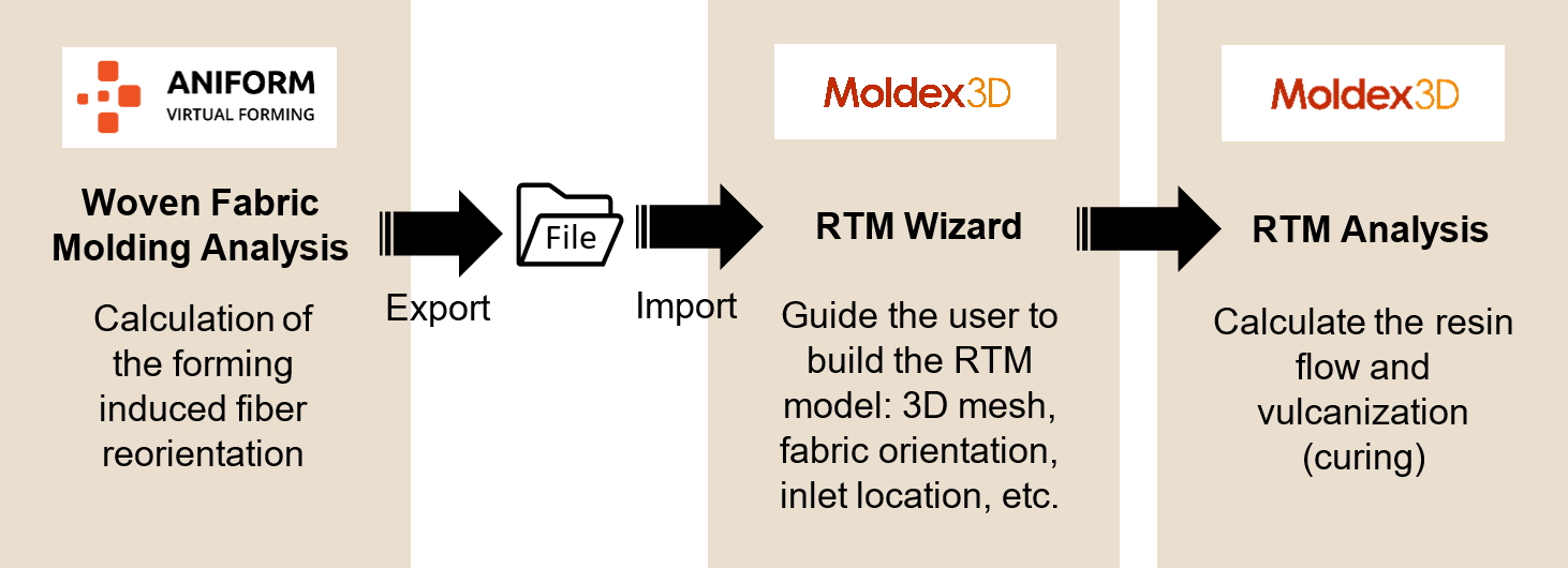
Fig. 1 The RTM simulation process using AniForm coupled with Moldex3D

Fig. 2 The Formed Woven Fabric simulated by AniForm
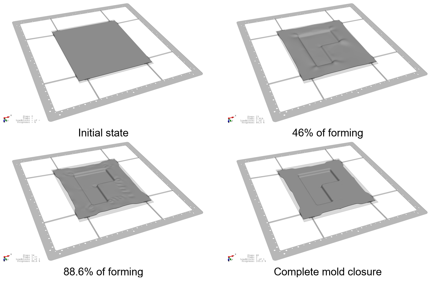
Fig. 3 AniForm forming predictions at various instances.
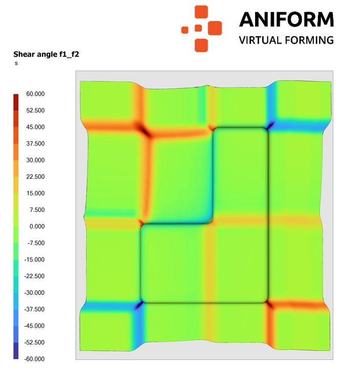
Fig. 4 Shear angle distribution predicted by AniForm.
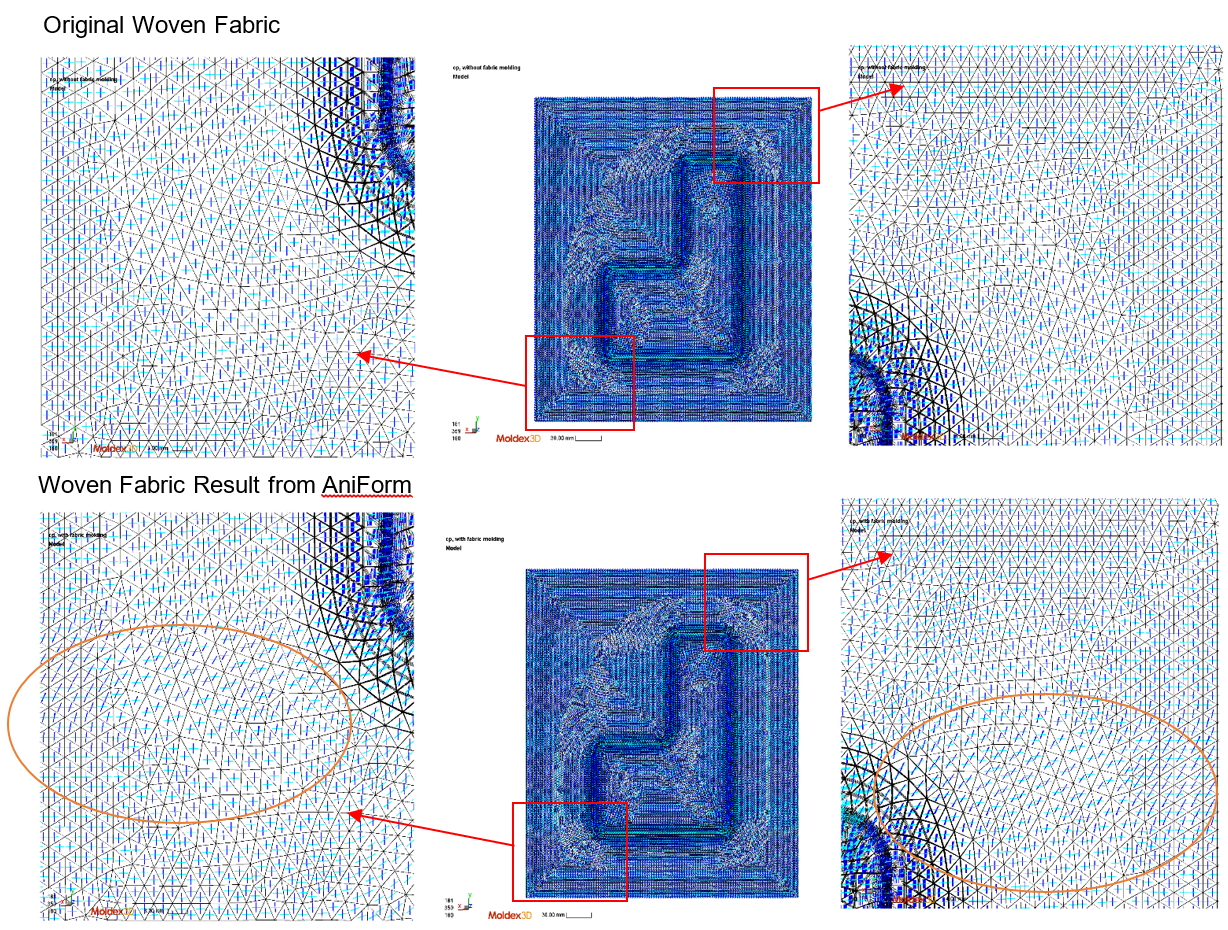
Fig. 5 Fabric Orientation
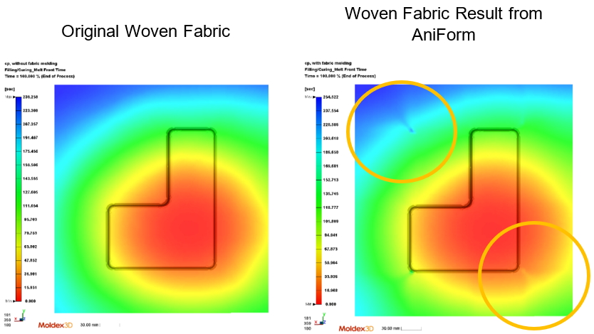
Fig. 6 Flow Front